As a supplier specializing in floating head heat exchangers, I’ve spent the last decade working side-by-side with plant operators, process engineers, and maintenance teams across refineries, petrochemical plants, and food processing facilities. One of the most consistent pain points I hear about? Flow distribution issues in these units. It makes sense: floating head exchangers are workhorses of industrial heat transfer, designed to handle high pressures, corrosive fluids, and frequent thermal expansion shifts—when their internal flow isn’t optimized, performance drops, energy costs spike, and even unplanned shutdowns follow. Over the years, I’ve seen both rookie mistakes and underutilized fixes that make a huge difference. Today, I want to pull back the curtain on what we’ve learned, from on-site troubleshooting to practical upgrades that actually move the needle on flow distribution. Floating Head Heat Exchangers
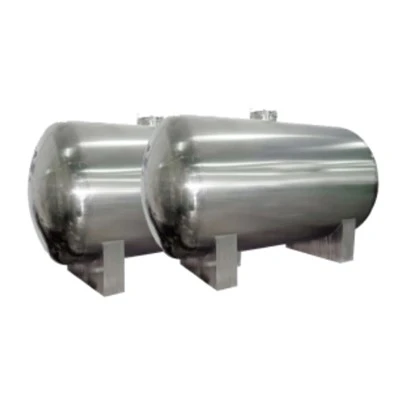
First, let’s ground this in why flow distribution matters so much for floating head exchangers specifically. Unlike fixed-tube units, floating head designs have a bundle that can expand and contract independently of the shell, which makes them ideal for extreme temperature differentials. But that same flexibility comes with a quirk: the shell side (where one fluid flows around the tubes) has a larger, more irregular internal volume than in fixed-tube exchangers. If that fluid doesn’t spread evenly across every tube, some tubes get too hot or too cold, others carry more than their share of flow, and you end up with what’s called “channeling.” Channeling isn’t just inefficient—it creates hot spots that corrode tubes faster, reduces overall heat transfer coefficient by as much as 20%, and can even trigger thermal fatigue cracks over time. I once worked with a mid-sized refinery that was losing $120,000 a year in extra fuel costs because their 10-year-old floating head exchanger was only running at 78% efficiency, all due to poor shell-side flow. That’s the kind of number that makes every operator sit up and listen.
So where do most flow distribution problems start? Inlet and outlet piping connections. I’ve seen so many units installed with inlet nozzles that are sized wrong, or placed at odd angles, or just plain too small for the flow rate they carry. For example, installing a 6-inch inlet nozzle on a unit sized for 8-inch flow leads to high inlet velocity that slams straight into one side of the shell, creating a jet that skips most of the tubes near the opposite wall. That’s a fixable mistake, but too often it’s overlooked during initial installation.
The first actionable step to improve flow distribution is auditing your existing inlet and outlet piping configuration. Don’t just guess—do a flow simulation or a physical inspection of nozzle alignment, velocity profiles, and potential pressure drop points. One trick we use is to check the velocity at the inlet nozzle: it should be between 1.5 and 3 m/s for liquid fluids, and 15 to 30 m/s for gas/vapor. If it’s higher than that, you’re creating a jet effect. If it’s lower, you’re probably having flow stagnation in the shell. I always tell teams to add straight pipe runs (no elbows, valves, or tees) at least 10 times the nozzle diameter upstream of the inlet, and 5 times downstream, to let the flow stabilize before it hits the exchanger. Elbows and fittings create turbulence that messes with flow symmetry—we saw a 12% improvement in flow uniformity on a food processing plant’s exchanger just by adding 8 feet of straight pipe upstream of the inlet, no other changes.
Next up: installing or optimizing flow distribution devices inside the shell. This is where our team at the supplier has done a lot of hands-on testing over the years, because generic distributors don’t work for every application. The two most common devices are perforated baffles and impingement plates, but each has specific use cases. Impingement plates are perfect for high-velocity inlet fluids (like hot gas streams) because they break the jet before it can hit the tube bundle. I once worked with a petrochemical plant that had a floating head exchanger handling 400°C vapor at 2.5 m/s velocity; the initial jet was eroding the leading row of tubes, and flow was so uneven that some tubes were 50°C hotter than others. We installed a custom impingement plate sized to cover 80% of the inlet nozzle cross-section, angled 15 degrees off the tube axis. Within three months, tube temperatures evened out to within 10°C, and erosion rates dropped by 70%.
Perforated distribution baffles, on the other hand, are better for liquid or mixed-phase flows where you need to spread flow across the entire shell cross-section, not just break a jet. The key here is not just drilling holes randomly—you have to match the hole size and pattern to your specific flow rate and tube layout. For example, if your shell has a triangular tube pitch (common in most floating head units), you want larger holes in the center of the distribution baffle and smaller holes near the walls, to counteract the natural flow that tends to cling to the shell’s inner surface and leave the center underfed. One mistake I see a lot is using a single perforated baffle at the inlet, but adding a secondary “support” distribution baffle 3 to 5 tube rows downstream can further reduce channeling. We tested this on a refinery’s crude oil exchanger, and flow uniformity improved by 18% after adding a second baffle—something the plant’s previous maintenance team had missed because they thought one was enough.
Wait, but what about tube-side flow? A lot of people fixate on shell side, but tube-side flow distribution is equally important for floating head exchangers, especially if you have multiple tube passes. If one pass has more flow than others, those tubes will be under stress, and heat transfer will suffer. The fix here is usually tube pass dividers and nozzle sizing, but there’s an additional trick for older units with damaged dividers. We’ve replaced rusted or poorly fitted divider strips with custom-machined stainless steel dividers that create tight seals between passes, preventing flow from leaking between passes. On a 4-pass floating head exchanger at a pharmaceutical plant, this fix alone boosted their tube-side heat transfer by 9% and reduced pressure drop by 12%—they were able to cut their pump energy use by $15,000 a year as a result.
Another underdiscussed factor: fouling buildup in the shell side. Over time, debris, scale, or sediment can collect on the distribution baffles or around the inlet nozzle, blocking holes or redirecting flow. This is a slow killer of flow distribution—most operators don’t notice it until efficiency drops by 10% or more. Preventive maintenance here isn’t just annual cleaning (though that helps); it’s installing strainers on the inlet piping to catch large debris, and designing distribution baffles with larger hole sizes (and regular cleaning access) to prevent clogging. I recommend scheduling a fouling inspection every six months for exchangers handling dirty fluids like crude oil or wastewater, because even a thin layer of scale on a perforated baffle can reduce flow through those holes by 30%.
For older floating head exchangers that are beyond simple fixes, there are more impactful upgrades. One of the most effective is tube bundle re-tubing with optimized tube layouts. For example, if your original unit has a square tube pitch (which is better for mechanical cleaning), switching to a triangular pitch (which increases heat transfer area and improves flow mixing) can fix flow channeling, as long as you adjust the shell diameter and baffles to fit the new layout. Another upgrade is variable pitch baffles—instead of using evenly spaced segmental baffles (the standard design), variable pitch baffles narrow the spacing near the inlet and outlet and widen it in the middle, which slows high-velocity inlet flow and speeds up slow flow in the center, creating a more uniform profile. We retrofitted a 20-year-old floating head exchanger with variable pitch baffles for a power plant, and their heat transfer efficiency jumped from 72% to 89%—that’s a 23% gain, all from baffles designed for their exact flow conditions.
I also can’t stress enough the importance of matching solutions to your specific application, not just using one-size-fits-all fixes. A flow distribution device that works for a water-cooled exchanger won’t work for a high-pressure hydrogen stream, for example. At our company, we don’t just sell parts—we do a full on-site assessment, measure flow rates, pressure profiles, and tube temperatures, then model the flow to find exactly where the bottlenecks are. Last year, we worked with a mid-sized chemical plant that was considering replacing a floating head exchanger because flow distribution was so bad. Instead of replacement, we installed a custom inlet nozzle with an integrated flow distribution insert, modified the baffles, and adjusted the straight pipe runs. The total cost was less than 15% of a new unit, and their efficiency went up 25%—they avoided a six-month lead time for a new exchanger, which would have cost them millions in lost production.
Of course, even the best design and upgrades won’t help if maintenance is inconsistent. A common mistake we see is teams skipping annual inspections of distribution devices or deferring minor repairs like leaky pass dividers. I always tell operators to build flow distribution checks into their regular maintenance schedule: every time you take the exchanger offline for cleaning, inspect the inlet nozzle for damage, check perforated baffles for clogs or warping, and verify that pass dividers are still sealed properly. Small issues caught early prevent big, costly problems later.
At the end of the day, improving flow distribution in floating head heat exchangers isn’t rocket science—it’s a mix of correct initial design, targeted upgrades, and consistent upkeep. The examples I’ve shared aren’t theoretical; they’re results from units we’ve worked with over the last decade, units that went from underperforming to meeting (or exceeding) their design specifications. If your floating head heat exchanger is suffering from channeling, uneven tube temperatures, or high energy costs, don’t write it off as a lost cause. Instead, partner with an experienced supplier that understands the unique needs of floating head units, to audit your flow and implement tailored solutions. We’re here to help you optimize your heat transfer, reduce energy use, and avoid unplanned downtime, so you can keep your operations running smoothly.

If you’re ready to tackle flow distribution issues with data-driven solutions for your floating head heat exchangers, we’re here to support you every step of the way. Reach out to our team today to schedule an on-site assessment or request a custom flow analysis.
Heat Exchanger References
- Kakac, S., Liu, H., & Pramuanjaroenkij, A. (2012). Heat Exchangers: Selection, Rating, and Thermal Design. CRC Press.
- Shah, R. K., & Sekulic, D. P. (2003). Fundamentals of Heat Exchanger Design. John Wiley & Sons.
- Gumley, P. (2006). Flow Distribution in Heat Exchangers: A Practical Guide. Professional Engineering Publishing.
- American Petroleum Institute. (2018). API 660: Shell and Tube Heat Exchangers for General Refinery Service.
- Hewitt, G. F., Shires, G. L., & Bott, T. R. (1994). Process Heat Transfer. CRC Press.
Shandong Meiling International Trading Co., Ltd.
We are one of the most professional floating head heat exchangers manufacturers and suppliers in China, featured by quality products and good service. Please feel free to wholesale advanced floating head heat exchangers made in China here from our factory. Customized orders are welcome.
Address: No. 998 Niushan Road, Linzi District, Zibo City, Shandong Province
E-mail: dingxiaoli@sdmeiling.com.cn
WebSite: https://www.ml-heatexchanger.com/
