Hey everyone, I’m Mike, and after 12 years as a planetary reducer supplier, I can tell you that the question I get asked most often isn’t about part numbers or lead times—it’s about calculating dynamic load capacity. A lot of folks come to me with a vague idea of what they need, but they don’t have a clear handle on how dynamic load works, and that’s where things go sideways fast. Underestimating dynamic capacity means premature reducer failure; overestimating means wasted money on an overbuilt unit that doesn’t fit your budget. Today, I’m breaking this down like I’d do for a new engineer on my team—no fancy jargon that doesn’t stick, just real-world steps that actually work. Planetary Reducer
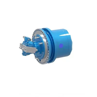
First, let’s knock out what dynamic load capacity even is, because so many folks mix it up with static capacity. Static capacity is the maximum load a reducer can hold without moving—think of a winch holding a parked trailer. Dynamic load capacity is different: it’s the maximum load the reducer can handle while operating continuously (or at a specified duty cycle) without failing due to fatigue. For planetary reducers, which are workhorses in robotics, conveyor systems, packaging equipment, and agricultural machinery, this isn’t a small detail. A robot arm in a pick-and-place line at Amazon? It cycles 10,000 times a day. If the reducer’s dynamic capacity is off, that line shuts down—costing thousands per hour. I’ve seen this firsthand: a food packaging customer once went with a cheap reducer that had a miscalculated dynamic load, and they had to replace 12 units in three months. They came back to us afterward, and we adjusted their calculations to get the right size and cut their failure rate to zero. That’s why this stuff matters.
Now, let’s get into the actual calculation. I always start by telling customers that this isn’t a one-size-fits-all formula—you have to pull data from your specific application, not a generic chart. Here’s the step-by-step process I use with every client:
Step 1: Map out your application’s load profile. This is non-negotiable. You can’t just plug in a single number and call it a day. Every motion has three types of load: radial (side-to-side, like a conveyor belt pulling against a roller), axial (forward/backward, like a screw driving a clamp), and torsional (twisting, like a robot arm rotating). For example, a concrete mixer’s reducer deals mostly with high radial and torsional load, while a drill press’s reducer has high axial load from the bit pressing into concrete. I ask clients to log every second of operation for a full work cycle, then break it into segments: startup (when load spikes), steady operation, and deceleration (another spike from inertia). Most of my older clients have these numbers from years of their equipment, but new ones have to track it for a week—no shortcuts here.
Step 2: Calculate the equivalent dynamic load (P). This is the number you plug into the standard dynamic load formula for rolling bearings, because planetary reducers rely on precision ball or roller bearings in their planet gears, sun gear, and output shaft. The formula I use is P = (X * Fr) + (Y * Fa), where Fr is radial load, Fa is axial load, and X and Y are factors from the bearing manufacturer’s catalog—not generic factors off the internet. Wait, but that’s for single bearings, right? Planetary reducers have multiple bearings, so you have to adjust this for the gear train’s load distribution. Here’s the catch: planet gears share load, so if you have 3 planets (common in most reducers), each carries roughly 1/3 of the total radial load, but that changes if one planet is worn. I tell clients to use the maximum load on the most heavily loaded component, not the average. Last year, a robotics integrator forgot this, used average load, and their reducer failed in 60 days—we fixed it by cranking in the peak component load, which was only 15% higher than average, but made all the difference.
Step 3: Factor in the dynamic load rating (C) of your reducer. This is the official number the manufacturer publishes, and it’s based on the bearing’s ability to handle 1 million revolutions (for ball bearings) or 10 million revolutions (for roller bearings) without fatigue. Wait—fatigue is key here. The dynamic load rating C isn’t about breaking the bearing; it’s about cumulative stress leading to small pits on the raceways, which cause noise and failure. The standard formula for fatigue life is L10 = (C / P)^p, where L10 is the life in millions of revolutions, and p is the exponent: 3 for ball bearings, 10/3 for roller bearings. Let’s test this with a real example: if your reducer uses ball bearings, p=3. If your equivalent dynamic load P is half the C rating, L10 = (2)^3 = 8 million revolutions. If your machine runs 1,000 revolutions per hour, that’s 8,000 hours of operation—about a year and a half. That’s too short for a packaging line that runs 24/7. So you need to adjust the ratio: if you want a 10-year life (87,600 hours), that’s 87,600 * 1,000 = 87.6 million revolutions. Rearranging the formula, C = P * (L10)^(1/p). So for p=3, C = P * (87.6)^(1/3) ≈ P * 4.44. That means your dynamic load rating needs to be 4.44 times your equivalent dynamic load to hit that 10-year life. I always round up to 5 times, just to add a safety factor—no one likes a panic call at 2 a.m. when a line goes down.
Step 4: Adjust for special duty factors. This is where a lot of online guides drop the ball. If your application has shock loads, high temperatures, or misalignment, you have to add a duty factor (let’s call it f_d) to your equivalent dynamic load P. Shock loads from startup, like a conveyor lifting a full pallet, can double your load for a few seconds. High temperatures over 100°C soften the bearing steel, reducing its effective C rating by 10-20%, so you have to bump up P by that amount. Misalignment from a poorly mounted motor or driven shaft can add 30-50% extra load, especially in planetary reducers where precision alignment is critical. Last quarter, a agricultural equipment customer had misalignment from a tractor’s vibration, and their initial calculation didn’t include a duty factor—their reducer’s life was cut in half. We adjusted the calculation with f_d=1.5 and swapped in a reducer with a higher C rating, and they haven’t had an issue since. I tell clients to never use a duty factor lower than 1.2 for most industrial apps, and 1.5 for heavy shock or vibration.
Wait, let’s make this concrete with a real-world example, not just math. Let’s say we have a conveyor system in a warehouse that runs 16 hours a day, 5 days a week, 50 weeks a year. We’ve measured the load: radial load Fr = 2,500 N, axial load Fa = 800 N, with low shock (f_d=1.2), and it uses ball bearings so p=3. The bearing catalog for a standard precision ball bearing gives X=0.56 and Y=1.2 for radial and axial load factors. First, calculate equivalent dynamic load P = (0.56 * 2500) + (1.2 * 800) = 1400 + 960 = 2360 N. Now, adjust for duty factor: P_adjusted = 2360 * 1.2 = 2832 N. Now, what life do we need? 16 hours/day * 5 days/week * 50 weeks/year = 4000 hours/year. Let’s target 10 years: 4000 *10 = 40,000 hours. The conveyor runs at 60 RPM, so total revolutions L10 needed = 40,000 * 60 * 60 = 24,000,000 revolutions. Now, solve for C: C = P_adjusted * (L10)^(1/3) = 2832 * (24)^(1/3). The cube root of 24 is ~2.88, so C = 2832 * 2.88 ≈ 8,156 N. So we need a planetary reducer with a dynamic load rating of at least 8,156 N. That’s exactly the kind of calculation I run for every new client—no guesswork, just numbers that add up.
But here’s a common myth I have to bust: some suppliers will quote a “static load capacity” and call it enough. Static load is only for when the machine is off. If your reducer is moving, dynamic load is what kills it. I once had a customer who ordered a reducer with a great static rating because it was cheap, but their application ran 8 hours a day—they had to replace it 5 times in a year before they realized the difference. Always, always, prioritize dynamic load capacity for operating machinery.
Another thing I hear all the time: “Why does planetary reducer dynamic load differ from a standard gear reducer?” Good question. Planetary reducers have multiple load-sharing planets, which makes them more compact, but the load is split unevenly when they’re operating under dynamic conditions. The sun gear interacts with the planet gears at different angles as they rotate, so the load on each bearing isn’t perfectly equal. That’s why I recommend using the planet with the highest load when doing calculations, not the average—standard gear reducers have a single gear pair, so their load calculation is simpler. I learned this the hard way early in my career when I sized a planetary reducer for a conveyor, used average planet load, and the most loaded planet’s bearing failed within a month. That mistake cost me a client for a while, but it taught me to be hyper-specific about load distribution in planetary gear trains.
Now, let’s talk about mistakes I see all the time that mess up dynamic load calculations. First, ignoring inertia during acceleration and deceleration. When a robot arm starts moving, it’s not just carrying the weight of the payload—it’s building up inertia, which adds to the dynamic load. For rotary applications, inertia is calculated as J = m * r² (for point masses) or more complex formulas for irregular shapes. If you don’t add inertia load, your P number is way too low. Second, using generic load factors from old textbooks. Every reducer’s bearings are different, so you have to use the exact X and Y factors from the bearing manufacturer’s spec sheet. Third, not accounting for lubrication. If your reducer is operating in high temperatures, or has a poor lubrication schedule, the effective dynamic load rating drops by 10-15%—I always build that into the safety factor. Fourth, overcorrecting with a huge safety factor. A 5x safety factor is standard, but 10x is overkill and wastes money. I’ve had clients come to me who added 10x safety factor just to be safe, and they were paying 30% more than they needed to for a reducer.
At the end of the day, calculating dynamic load capacity isn’t about memorizing formulas—it’s about understanding your application’s unique needs, pulling accurate data, and adjusting for real-world conditions. It’s the difference between a reducer that runs for 10 years without a hitch and one that dies before its first anniversary. That’s why as a planetary reducer supplier, I don’t just ship parts—I work through these calculations with every client, walk them through the numbers, and make sure they have exactly what they need, no more, no less.

If you’re struggling to size a planetary reducer for your next project, or you’ve had issues with premature failures, don’t guess at the numbers. Reach out, and let’s work through the load profile together. We can pull your operation data, run the dynamic load calculation, and find the right reducer that fits your budget and your needs, so you don’t have to deal with downtime or wasted money. You don’t have to go it alone on this—after 12 years, I’ve seen every scenario, and I can help you avoid the mistakes I made early on.
Planetary Reducer REFERENCES
- Shigley, J. E., Mischke, C. R., & Budynas, R. G. (2004). Standard Handbook of Machine Design. McGraw-Hill.
- SKF Group. (2020). Rolling Bearings: Dynamic Load Capacity and Fatigue Life Calculations. SKF Engineering Manual.
- American Gear Manufacturers Association (AGMA). (2018). Standard for Planetary Gear Units—Rating Method. AGMA 6012-B18.
Ningbo Tuona Transmission Equipment Co., Ltd.
As one of the most professional planetary reducer manufacturers and suppliers in China, we have world-leading production equipment and strong manufacturing capabilities. Please rest assured to buy bulk customized planetary reducer from our factory. Contact us for more details.
Address: Room 1602, Unit 6, Building 4, Litang Jingyuan, Haishu District, Ningbo City
E-mail: 15990217848@163.com
WebSite: https://www.tuonadrive.com/
